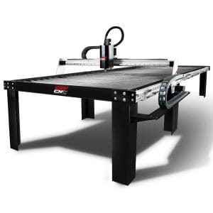
Major Components of a CNC Plasma Table
The development of the CNC table is an incredible contribution to the manufacturing industry. Almost every manufacturing industry uses CNC tables. With an increase in the competitive surroundings and demands, the demand for CNC usage has increased to a greater extent. CNC system consists of major components with functionality that is blended into synchronous mode. Let’s have a look at these main components of a CNC plasma table!

- Part program: This component is a sequence of coded directions required to create a part. It controls the action of the machine and on/off control of supplemental functions such as coolant and spindle rotation. The coded commands are formed of numbers, letters, and symbols.
- Input Devices: Input devices are in a job to enter the part program in the CNC machine. There are three commonly used input devices, and these are magnetic tape reader, punch tape reader, and computer via RS-232-C communication.
- Machine Control Unit (MCU): The MCU is the core of a CNC system. It is made of electronics elements and can interpret after reading the program instructions, after which, this can transform them into the mechanical activities of the specific devices. The control unit, thus, is the crucial link between the machine tool and the program. It operates the machine with the help of the given instructions.
- It works to read the commands.
- It works to decode the commands.
- It works to implement insertions to generate axis motion controls.
- It works to feed the axis motion commands to the amplifier circuits for driving the axis mechanisms.
- It works to get the feedback signs of position and velocity for each drive axis.
- It works to perform auxiliary control roles such as coolant or spindle on/off and tool settings.
- Machine Tool: The actual methods for machining are provided by the machine tool. This can be any device like milling machine, drilling, lathe, or any other machine. This is the element that is regulated in the CNC. These devices also have the control panel or the control console that contains the dials and switches which the operator uses to control the machine. You also have displays where the necessary information is revealed.
- Driving System: This system of a CNC tool includes drive motors, amplifier circuits, and ball lead screw. The machine control unit supplies the signals of each axis to the amplifier circuits. The control signals are then amplified to trigger the spin motors. And the triggered spin motors turn the ball lead screw to place the machine table.
- Feedback System: This system is also known as the measuring method. It uses state and velocity transducers to control the point at which the cutting tool is positioned at any moment. The machine control unit uses the difference between reference signals and feedback signals to produce the control signals for adjusting position and speed faults.
- Display Unit: Display unit is a monitor that is used to display the commands, programs, and other valuable data of the CNC machine.


Comments
Post a Comment